Garrattfan's Modelrailroading Pages
Fairlie Merddin Emrys
5.4 Gearbox
|
|
 |
|
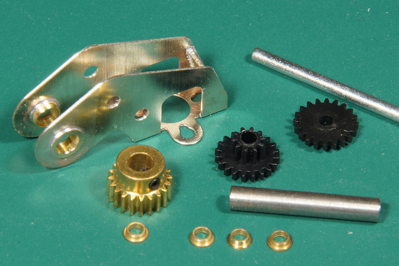
Mechanically the gearbox is the heart of the loco. The gearbox is folded and I provided an extra piece of nickel silver sheet in the top of the gear box to keep it in the correct shape. Before soldering neasure carefully is the angle of the gearbox are both exactly 90 degrees. The holes for the axle bushes are reamed and the axle bushes are secured with a quick pass of the soldering iron.
|
|
 |
|
 |
Here I missed out on the instructions. For this equation is my mind: Bushes + axle + hole = ream hole until bush fits.
So I reamed and reamed... and reamed......and reamed. I found it surprising unusual as your kit is always very accurate (it should have rung a bell). Once I soldered the bushes in the side of the gearbox I discovered in the instructions that the bushes (collars a you call them) were intended as a spacer inside the gearbox. |
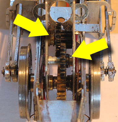 |
Fig. 38 in the instructions was very clear about that. Oopsy. |
 |
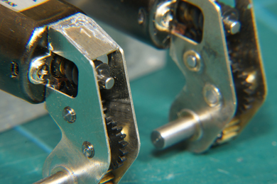
Now what. There was no turning back as the holes were way too big by now. And I also had a shortage of spacers. Based in fig 38 I fabricated two spacers from brass tube to serve the same purpose. I runs very well. There seems to be a lot of tplay in the mechanism but that is the nature of a macro photo, remember that the distance between the gearbox sides is just 5.7 mm!
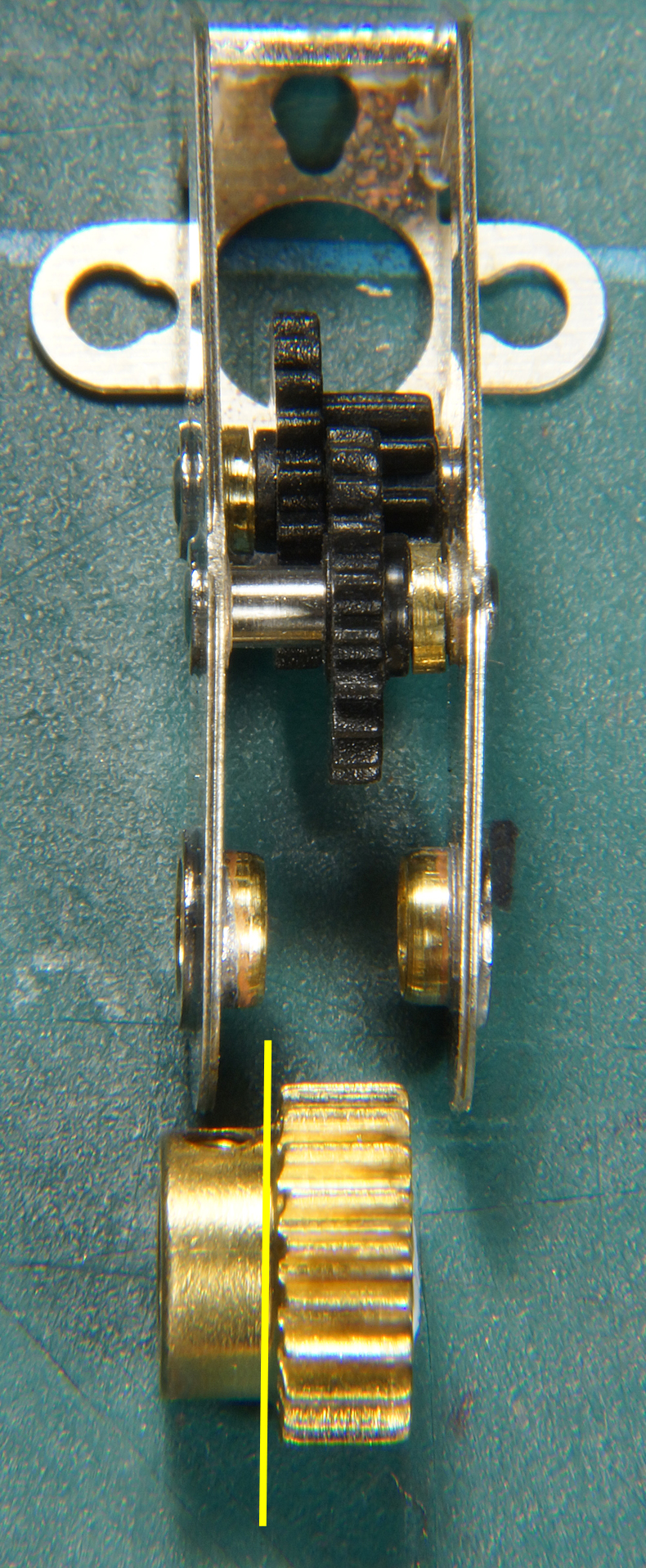
Next thing to decide is what to do with the brass gear. The brass main gear included in the kit is of a different type than on fig 38. The latter shows a simple gear and mine has a collar with a hex screw in it. There are two ways to go. 1. File the collar down until I get to the yellow line. But that will make securing the gear on the axle difficult as there is very little room to add glue. Advantage is that the gear will sit in the middle 2. The second way is to file the bushes down to the gearbox sides and insert the complete brass gear and fasten it with the hex screw. The gear will then sit slightly off center, but I think that is no problem. Small issue is that the gearbox allows 5.7 mm inside and that the gear is 6.0, so a little narrowing is due anyway. I turned to EDM Models for advice. Again the answer was swift and good.
Your kit has the more recent gear in it as its easier to secure – plus we couldn't get any more of the other sort. Don't get hung up on gears being central.
With the top gear more central you may have to ease the motor mount holes upwards to optimise the mesh with the worm |
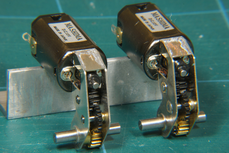
That said I thinned the brass gear a bit by sanding it on a coarse sanding stick, than a finer and finally very fine emery paper. I took about 0.3 mm off, just enough to fit easily between the gearbox sides. I filed the axle bushes down to the frames side's inside. Then I assembled the gear with the spacers in place and fixed the intermediate axles with a drop of epoxy from the outside. It ran lovely. The second gearbox followed suit, but this time I reamed the holes of the intermediate axles only modestly and glued the axle directly in the gearbox sides as per the instructions. This saved a lot of time. The bushes only served as spacers |
|
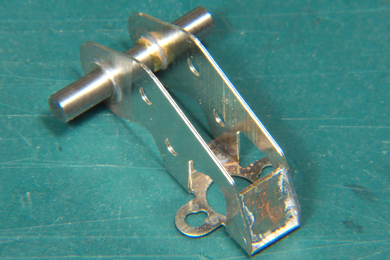
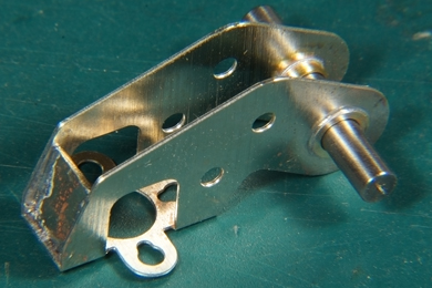
The first gearbox with the bushes soldered in the sides and then the intermediate axles glued in them. |
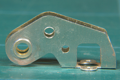
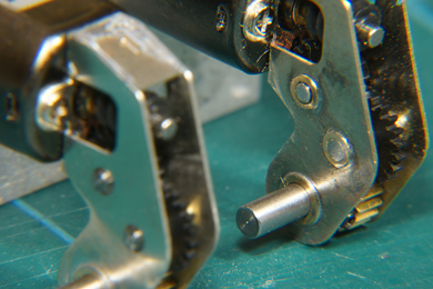
The second gearbox with the intermediate axles glued directly into the sheet metal of the gearbox sides. |
Another job done. |
|

Sign my
GuestBook